You could find more inforamtion about this challenge at this link. I am going to propose three different approaches to solve this challenge, and those approaches range from hardware to emulation, instead of just static analysis.
About this challenge
This is a password locker firmware built upon stm32f103c8t6, which is sort of ubiquitous in today’s iot hacking tutorials ;)
Four GPIO channels (GPIO_PA1, GPIO_PA2, GPIO_PA3, GPIO_PA4) are provided for users to type in passwords, which are representing number 1 to 4:
- the format of flag1 is SCTF{passowrd}
- once a correct password is provided, the firmware sends flag2 via UART-TX at PA9
Tips: interrupt vector table, datasheet, jtag allowed, dynamically debuggable, trigger mode on pushing botton.
Firmware reversing
According to cortex-m convention, there are stack address and the reset interrupt service routine (ISR) at the first eight bytes. Following through reset ISR, we finally identify main function inhabiting at 0x08000428. Beware that 0x8000000 is base address for code section. Another intuition to support this identification is a super loop within this function. Overall, the analyzed ghidra zip file is here.
SVD
In order to better understand how peripherals are setup in the firmeware logic, we use svd-loder in ghidra scripts to automatically create MMIO ranges for all peripherals. Download a svd file of this MCU at the link. Search the script svd-loder. Once this script had been executed, it is fairly easy to identify Uart_Send. Moreover, the firmware sends SCTF{ before diving into an infinite loop.
void main(void)
{
  undefined *puVar1;
  undefined *peripheral;

  FUN_080002f0();
  peripheral = PTR_RCC_08000594;
  *(undefined4 *)(PTR_RCC_08000594 + 0x18) = 0;
  *(uint *)(peripheral + 0x18) = *(uint *)(peripheral + 0x18) | 1;
  puVar1 = PTR_RCC_08000594;
  *(uint *)(PTR_RCC_08000594 + 0x18) = *(uint *)(peripheral + 0x18) | 0x4004;
  *(undefined4 *)(puVar1 + 0x14) = 1;
  peripheral = PTR_GPIOA_0800059c;
  *(dword *)PTR_GPIOA_0800059c = DWORD_08000598;
  *(undefined4 *)(peripheral + 4) = 444444B4;
  *(undefined4 *)(PTR_GPIOA_0800059c + 0xc) = 0b00011110;
  *(undefined4 *)PTR_EXTI_080005a4 = 0b00011110;
                    /* falling trigger enabled */
  *(undefined4 *)(PTR_EXTI_080005a4 + 0xc) = 0b00011110;
  peripheral = PTR_AFIO_080005a8;
  *(undefined4 *)(PTR_AFIO_080005a8 + 0xc) = 0;
  *(undefined4 *)(peripheral + 0x10) = 0;
  FUN_080003b0(7);
  FUN_080003b0(8);
  FUN_080003b0(9);
  FUN_080003b0(10);
  peripheral = PTR_RCC_08000594;
  *(uint *)(PTR_RCC_08000594 + 0xc) = *(uint *)(PTR_RCC_08000594 + 0xc) | 0x4000;
  *(uint *)(peripheral + 0xc) = *(uint *)(peripheral + 0xc) & 0xffffbfff;
  peripheral = PTR_USART1.BRR_080005ac;
  *(undefined2 *)PTR_USART1.BRR_080005ac = 0x271;
  *(undefined2 *)(peripheral + 4) = 0x2008;
  UART_Send(L'S');
  UART_Send(L'C');
  UART_Send(L'T');
  UART_Send(L'F');
  UART_Send(L'{');
  *(undefined2 *)(PTR_USART1.BRR_080005ac + 0xc) = 0x80;
  peripheral = 40020000_DMA;
  *(undefined4 *)(40020000_DMA + 0x50) = 0x20000000;
  *(undefined **)(peripheral + 0x4c) = PTR_USART1.BRR_080005ac + -4;
  *(undefined4 *)(peripheral + 0x48) = 0x1e;
  *(undefined4 *)(peripheral + 0x44) = 0x492;
  FUN_080003b0(0xe);
  do {
                    /* WARNING: Do nothing block with infinite loop */
  } while( true );
}
Peripheral configuration
A few question arise. How is GPIO port A configured and used? What about DMA? Datasheet details everything we need.
Let us research into operation mode first:
*(dword *)GPIOA_40010800 = DWORD_08000598 //44488884h;
According to datasheet, this address sets up output data registers to activate some of pins in output mode. This case configures PA1 to PA4.
*(undefined4 *)PTR_EXTI_080005a4 = 0b00011110;
This enables external interrupts for four pins mentioned above, which means that the program will jump to a corresponding routine once any of those bottons is pushed.
The interrupt vector table indicates where they are:
        0800005c 6d 01 00 08     addr       EXIT1+1
        08000060 ad 01 00 08     addr       EXIT2+1
        08000064 e5 01 00 08     addr       EXIT3+1
        08000068 2d 02 00 08     addr       EXIT4+1
*(undefined4 *)(PTR_EXTI_080005a4 + 0xc) = 0b00011110;
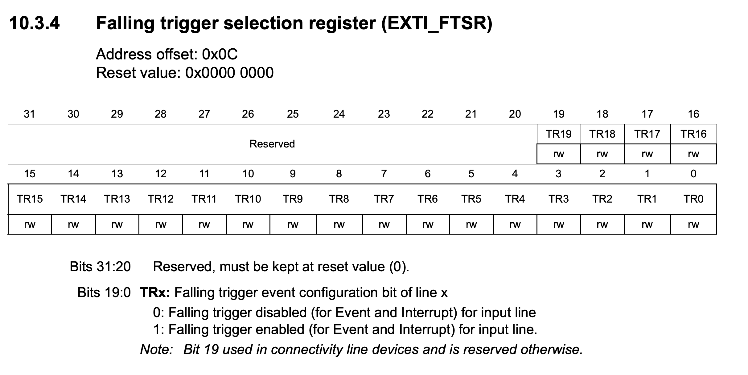
This setup is really crucial since it specifies falling trigger mode to be enabled. This means that we need to create a falling edge to trigger those interrupts.
 .
.
Those ISRs will check if a user pushes bottons in a correct order. If so, flag2 will be sent to UART-TX via DMA. For example, EXIT2 does data transmission by enabling DMA.
void EXIT3(void)
{
  *DAT_0800021c = 8;
  if (*2000003C == '\x06') {
    *(undefined *)(20000000 + 0xc) = '_';
    // enable DMA
    *(uint *)(40020000 + 0x44) = *(uint *)(40020000 + 0x44) | 1;
    *2000003C = *2000003C + '\x01';
  }
  ...
}
  peripheral = 40020000_DMA;
  *(undefined4 *)(40020000_DMA + 0x50) = 0x20000000;
  *(undefined **)(peripheral + 0x4c) = PTR_USART1.BRR_080005ac + -4;
  *(undefined4 *)(peripheral + 0x48) = 0x1e;
  *(undefined4 *)(peripheral + 0x44) = 0x492;
Here is crucial as well, because we directly figure out a source or destination address over entire DMA data transmission.
First approach - static analysis
Throughout the previous analysis, we roughly know how to acquire its password by checking four ISRs for external interrupts. So, it is way easy to get the first flag ;(
Furthermore, password has been presented already in the main:
DAT_080005a4[4] = DAT_080005a4[4] | 2;
delay(1);
DAT_080005a4[4] = DAT_080005a4[4] | 0x10;
delay(1);
DAT_080005a4[4] = DAT_080005a4[4] | 0x10;
delay(1);
DAT_080005a4[4] = DAT_080005a4[4] | 4;
delay(1);
DAT_080005a4[4] = DAT_080005a4[4] | 0x10;
delay(1);
DAT_080005a4[4] = DAT_080005a4[4] | 2;
delay(1);
DAT_080005a4[4] = DAT_080005a4[4] | 8;
delay(1);
Hence, we could naturally listen on PA9 for the second flag after the device finishes reboot. This is damn boring~~
So, I patched those silly code snippets that sort of leak password in order to have more fun ;)
The other two approaches are propsed upon the patch version.
Second approach - hardware fuzzing
We already know passwords consist of 7 digits. Each digit could only be between 1 and 4. I do know firmware is not easily accessible or acquirable in most cases. For example, a firmware binary is stored in NOR flash or NAND flash, which makes it a bit harder to dump the firmware binary.
When it comes to this challenge, I leverage hydrabus to write down a script to automatically perform hardware-based fuzz testing of this device. Beforehand, I have already burned this patched firmware in my blue pill board, which uses the exactly same MCU as this challenge does. Basically, this testing will go through 16384 test cases in worst case. So, in order to guaratee whether sinals generated by hydrabus could properly simulate a botton push, I had only tested the correct password and acquired flag2.
 .
.
Furthermore, I did a lot of work to check if GPIO edges are generated correctly with the help of openocd to debug the running device and read a value in memory.
 .
.
Nonetheless, writing a script to bruteforce this passowrd is not that hard:
#!/usr/bin/env python3
# pip install hexdump
# pip install pyserial

import hexdump
import serial
import struct
import time
import itertools
# Fix the values based on datasheet and hydrabus documentation
# Search for HydraFW Binary Mode SPI
HB_MODE_PIN = b'\x09' # Set Hydrabus to SPI mode

DEVICE = '/dev/ttyACM0' # Set USB device

# Open serial port
hydrabus = serial.Serial(DEVICE, 115200)

#Open binary mode
for i in range(20):
	hydrabus.write(b"\x00")
if b"BBIO1" not in hydrabus.read(5):
    print("Could not get into binary mode")
    quit()

# Switch to PIN mode
hydrabus.write(HB_MODE_PIN)
if b"PIN" not in hydrabus.read(4):
	print("Cannot set PIN mode")
	quit()

# Disable pull
# hydrabus.write(b"\x04")
# hydrabus.write(b"\xff")
# if hydrabus.read(1):
# 	print("Disable pull on all pins")

# Set Pin in output mode
hydrabus.write(b"\x03")
## all pins switch to output mode
hydrabus.write(b"\x00")
if hydrabus.read(1):
	print("PA0-7 in output mode")

# Set all pins as high
hydrabus.write(b"\x08")
hydrabus.write(b"\xff")
if hydrabus.read(1):
	print("set all pins as high")

def pulse_pin(pin):

	# Read pin state
	hydrabus.write(b"\x02")
	if hydrabus.read(1):
		cur_state = int.from_bytes(hydrabus.read(1) ,"little")
		print(f"cur_state: {hex(cur_state)}")

	# Get pin state
	pin_state = cur_state & (1 << pin)
	if pin_state == 0:
		hydrabus.write(b"\x08")
		hydrabus.write((cur_state | (1 << pin)).to_bytes(1, "little"))
		if hydrabus.read(1):
			print(f"pulse pin {pin} from low")
		time.sleep(0.5)
		## recovery to orginal state
		hydrabus.write(b"\x08")
		hydrabus.write(cur_state.to_bytes(1, "little"))
		if hydrabus.read(1):
			print("recovery")
	else:
		hydrabus.write(b"\x08")
		hydrabus.write((cur_state & (~(1 << pin))).to_bytes(1, "little"))
		if hydrabus.read(1):
			print(f"cur_state: {cur_state}")
			print("pulse PIN {} from high to 0x{:02x}".format(pin, cur_state & (~(1 << pin))))
		time.sleep(0.5)
		## recovery to orginal state
		hydrabus.write(b"\x08")
		hydrabus.write(cur_state.to_bytes(1, "little"))
		if hydrabus.read(1):
			print("recovery")

	time.sleep(1)


PA = {"PA0": 0, "PA1": 1, "PA2": 2, "PA3": 3, "PA4": 4, "PA5": 5, "PA6": 6, "PA7": 7}
PULLUP = 1
PULLD0WN = 0

time.sleep(5)

cmd = input("please provide a command: ")
if cmd != "continue":
	print("quit")
	hydrabus.write(b'\x00')
	hydrabus.write(b'\x0F\n')
	quit()

# set 0x2000003c as 0 since the firmware logic has already printed flag via uart,
# which would fix the value at this address as 7
# pulse_pin(PA["PA0"])


def reset_password_checking_state():
  pulse_pin(PA["PA0"])
  pulse_pin(PA["PA0"])

codes = ['PA1', 'PA2', 'PA3', 'PA4']
combinations = list(itertools.product(codes, repeat=7))
for combination in combinations:
  for each_code in combination:
    pulse_pin(PA[each_code])
  reset_password_checking_state()

"""
pulse_pin(PA["PA0"])
pulse_pin(PA["PA3"])
pulse_pin(PA["PA3"])
pulse_pin(PA["PA1"])
pulse_pin(PA["PA3"])
pulse_pin(PA["PA0"])
pulse_pin(PA["PA2"])
"""

hydrabus.write(b'\x00')
hydrabus.write(b'\x0F\n')
Basically, this script sets up hydrabus as a binary mode, that allows us to control it programatically. It then makes four pins to be high before the stage of fuzz testing. Fuzz testing iterates all combinations over four items in a list of candidate password digits.
Due to the firmware that expects a falling edge from any button push, we need to simulate this behavior in hydrabus as well. Hence, pulse_pin will generate a falling edge before recoverying back to original voltage
Notably, we need to reset password checking state each time we test one case, because this firmware internally measure checking by a counter. We need to force this counter as 0 for each test case.
Of course, this input generatation is very ineffective since we gain no feedback on which test case will progress this password checking, or reach more meaningful basic blocks. The chance of hitting all digits is only 1 out of 16384, which is fine for software-based fuzzing but a definitely nightmare.
Hardware setup
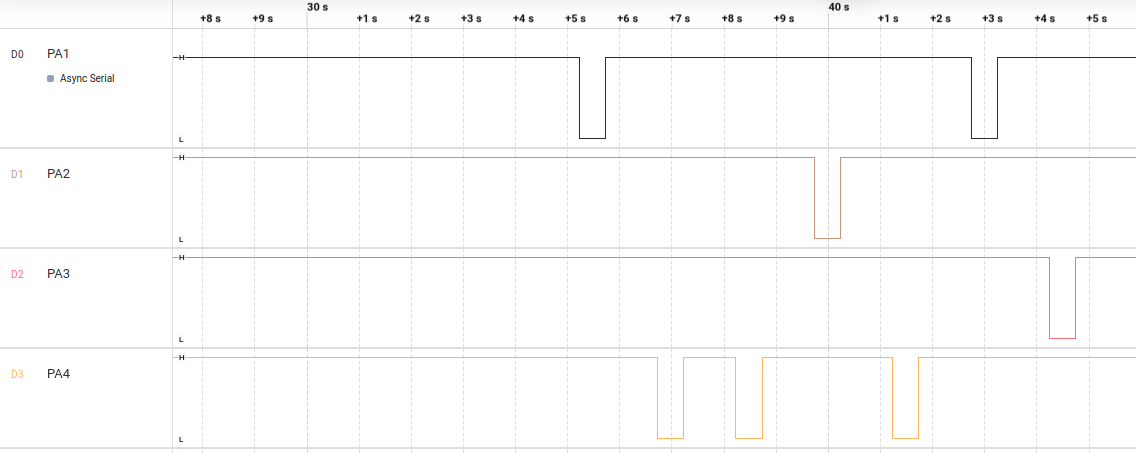
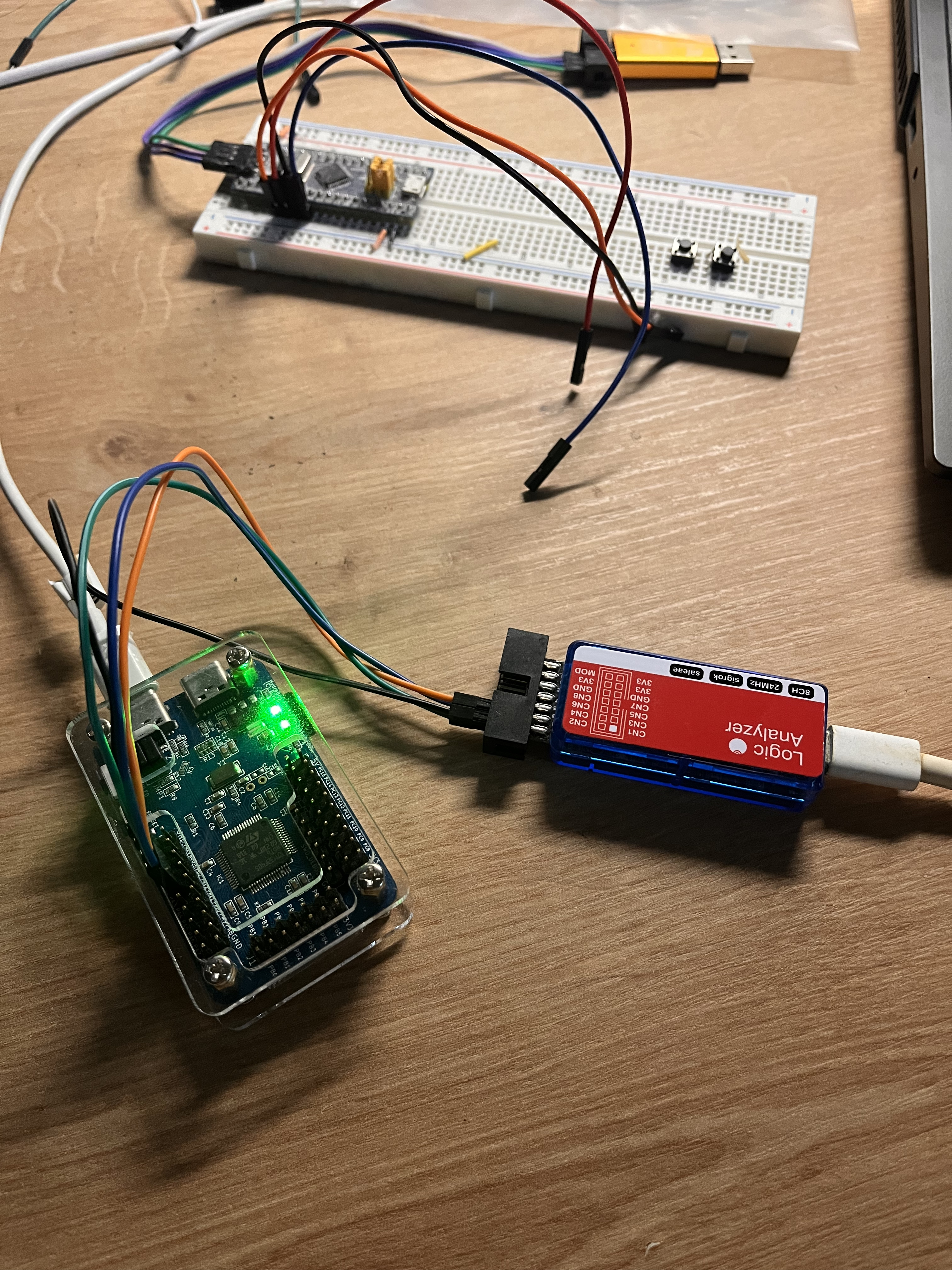
The first picture indicates a testing of generated signals from hydrabus using logic analyzer
 .
.
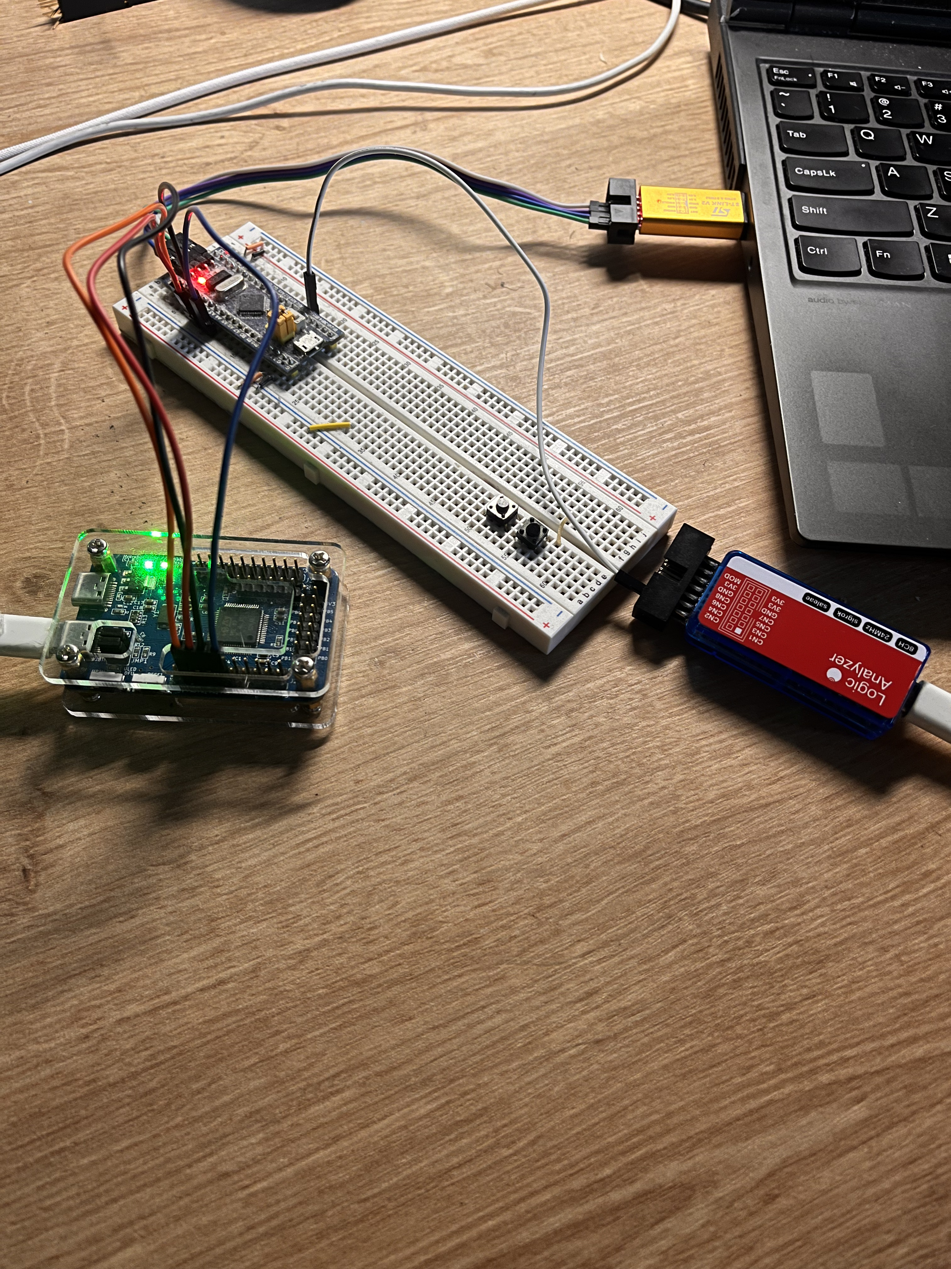
In the second picture, four pins of hydrabus are connected to blue pill, while logic analyzer connects one wire to blue pill to monitor any output from UART-TX.
 .
.
Feedback-driven hardware fuzzing by avatar2 + hydrabus
The key idea is to get access to the value at 0x2000003c, in order to identify whether the currently pressed button is the right one. In this case, I use Avatar2 that offers a full control over openocd, and this feature could seamlessly be incorporated into the previous script.
To enable a connection between the blue pill and openocd, we need to provide a configuration file for openocd. According to most online tutorials, people usually connect st-link to their devices, then establish connection via openocd by providing two configuration files, including one for st-link and another for the blue pill. However, avatar2 only accepts one argument to specify a configuration file. Hence, I educativelly consolidated two files as the whole one and it worked well. Note that the content of the st-link configuration file should always be placed at the beginning, otherwise, PC can’t identify st-link for further connection.
Furthermore, the most crucial point is to snapshot program states, so as to roll back to the last success point and continue fuzzing from there.
Consequently, it just take a few mintinues to bruteforce the right order of button press.
#!/usr/bin/env python3
# pip install hexdump
# pip install pyserial

import hexdump
import serial
import struct
import time
from avatar2 import *
from os.path import abspath


# Fix the values based on datasheet and hydrabus documentation
# Search for HydraFW Binary Mode SPI
HB_MODE_PIN = b'\x09' # Set Hydrabus to SPI mode

DEVICE = '/dev/ttyACM0' # Set USB device


# Open serial port
hydrabus = serial.Serial(DEVICE, 115200)

#Open binary mode
for i in range(20):
	hydrabus.write(b"\x00")
if b"BBIO1" not in hydrabus.read(5):
    print("Could not get into binary mode")
    quit()

# Switch to PIN mode
hydrabus.write(HB_MODE_PIN)
if b"PIN" not in hydrabus.read(4):
	print("Cannot set PIN mode")
	quit()

# Set Pin in output mode
hydrabus.write(b"\x03")
## all pins switch to output mode
hydrabus.write(b"\x00")
if hydrabus.read(1):
	print("PA0-7 in output mode")

# Set all pins as high
hydrabus.write(b"\x08")
hydrabus.write(b"\xff")
if hydrabus.read(1):
	print("set all pins as high")

def pulse_pin(pin):

	# Read pin state
	hydrabus.write(b"\x02")
	if hydrabus.read(1):
		cur_state = int.from_bytes(hydrabus.read(1) ,"little")
		print(f"cur_state: {hex(cur_state)}")

	# Get pin state
	pin_state = cur_state & (1 << pin)
	if pin_state == 0:
		hydrabus.write(b"\x08")
		hydrabus.write((cur_state | (1 << pin)).to_bytes(1, "little"))
		if hydrabus.read(1):
			print(f"pulse pin {pin} from low")
		time.sleep(0.5)
		## recovery to orginal state
		hydrabus.write(b"\x08")
		hydrabus.write(cur_state.to_bytes(1, "little"))
		if hydrabus.read(1):
			print("recovery")
	else:
		hydrabus.write(b"\x08")
		hydrabus.write((cur_state & (~(1 << pin))).to_bytes(1, "little"))
		if hydrabus.read(1):
			print(f"cur_state: {cur_state}")
			print("pulse PIN {} from high to 0x{:02x}".format(pin, cur_state & (~(1 << pin))))
		time.sleep(0.5)
		## recovery to orginal state
		hydrabus.write(b"\x08")
		hydrabus.write(cur_state.to_bytes(1, "little"))
		if hydrabus.read(1):
			print("recovery")

	time.sleep(1)


PA = {"PA1": 0, "PA2": 1, "PA3": 2, "PA4": 3}

time.sleep(5)

cmd = input("please provide a command: ")
if cmd != "continue":
	print("quit")
	hydrabus.write(b'\x00')
	hydrabus.write(b'\x0F\n')
	quit()

openocd_cfg = abspath("./stlink-stm32f1x.cfg")

avatar = Avatar(arch=ARM_CORTEX_M3, output_directory="/tmp/stm32f103")

stm32f103 = avatar.add_target(OpenOCDTarget, openocd_script=openocd_cfg)

avatar.init_targets()

known_password = []

left_guess = 7

bkt = stm32f103.set_breakpoint(0x8000590)
stm32f103.cont()
stm32f103.wait()
stm32f103.remove_breakpoint(bkt)

# now, the program runs into a super loop
prev_success = False

while left_guess != 0:

    sleep(.5)

    combinations = list(PA.keys())

    while len(combinations):
        # make sure the program remains in the superloop, otherwise there might be hitting our watchpoint before it reaches to the right place.
        bkt = stm32f103.set_breakpoint(0x8000590)
        stm32f103.cont()
        stm32f103.wait()
        stm32f103.remove_breakpoint(bkt)

        # now, it is in the super loop. Good to set a watchpoint
        bkt = stm32f103.set_watchpoint(0x2000003c)

        # adjust current program in statefulness if last guess goes wrong
        if not prev_success and len(known_password) != 0:
            for known_digit in known_password:
                bkt = stm32f103.set_watchpoint(0x2000003c)
                pulse_pin(PA[known_digit])
                stm32f103.cont()
                stm32f103.wait()
                stm32f103.remove_breakpoint(bkt)

            print("{} makes current counter value: {}".format(" ".join(known_password), stm32f103.rm(0x2000003c, 4)))

            bkt = stm32f103.set_watchpoint(0x2000003c)

        bruteforce_digit = combinations.pop()

        pulse_pin(PA[bruteforce_digit])

        stm32f103.cont()
        stm32f103.wait()
        stm32f103.remove_breakpoint(bkt)

        # check if this guess is right
        if stm32f103.rm(0x2000003c, 4) == 0:
            # wrong one
            print("guess wrong")
            prev_success = False
            time.sleep(.5)
            continue

        prev_success = True

        known_password.append(bruteforce_digit)

        left_guess -= 1

        print(f"guess one right, and {left_guess} are left to guess")

        break

print("password:", " ".join(known_password))

stm32f103.cont()
avatar.shutdown()
hydrabus.write(b'\x00')
hydrabus.write(b'\x0F\n')
![]() .
.
Third approach - rehosting with fuzzware
Re-hosting is a good approach in case of devices that do not place a high demand on time-critical execution. We benefit a lot from this approach, by configuring interrupt controllers to trigger interrupts somehow, guding fuzz testing based on information gained from emulator’s instrumentation, and so on.
Create a yaml file for configuration:
include:
- ./../../configs/hw/cortexm_memory.yml

memory_map:
  text:
    base_addr: 0x8000000
    file: ./patched_firmware.bin
    permissions: r-x
    size: 0x614
    is_entry: True

interrupt_triggers:
  trigger:
    every_nth_tick: 0x400
    fuzz_mode: fuzzed
arch: ARMCortexM
endianness: LE
use_nvic: true
use_timers: false
use_systick: false
It is worthwhile to notice that fuzz_mode on the interrupt trigger configuration must be fuzzed, otherwise we can’t guarantee randomness on interrupt generation.
Beware that we need to import a binary rather than Hex file because fuzzware can’t resolve this format.
Furthermore, we also need to create a file milestone_bbs.txt in the same level folder to record milestone basic blocks to figure out whether we need to continue running this testing or reach those meaningful program points.
80001f2
0x80001f2 is the basic block when the last digit is right against password checking.
Use the command fuzzware pipeline --silent-workers -n 8 to perform fuzz testing.
Fortunately, it just took a short while until I hit this milestone bb.
[08-04 17:20:11 INFO] pipeline.py - Current Pipeline Status (main002)
Translation blocks covered (missing BB ground truth!): 82. Milestones covered: 1 / 1 (100.0%)
Current jobs in Queue (trace gen/state gen/model gen): 0/0/0
Current fuzzer stats:
[1] crashes: 0. execs/second: 20.66 (overall: 16.00)
[2] crashes: 0. execs/second: 41.18 (overall: 32.00)
[3] crashes: 0. execs/second: 20.74 (overall: 16.00)
[4] crashes: 0. execs/second: 38.51 (overall: 32.00)
[5] crashes: 0. execs/second: 50.00 (overall: 32.00)
[6] crashes: 0. execs/second: 38.60 (overall: 32.00)
[7] crashes: 0. execs/second: 37.87 (overall: 32.00)
[8] crashes: 0. execs/second: 37.87 (overall: 32.00)
Use the command fuzzware cov 0x80001f2 to search input that reaches this basic block.
fuzzware cov 0x80001f2
[08-04 17:22:15 INFO] __init__.py - Got projdir: /home/user/fuzzware/targets/pw-recovery/STM32F103/fuzzware-project
Resolved basic block addresses: 0x80001f2
Set a breakpoint when replay a testing with this input:
fuzzware replay ./fuzzware-project/main002/fuzzers/fuzzer1/queue/id:000003,orig:id:000083,src:000065,op:havoc,rep:8,+cov -b 0x80001f2

ipdb> uc.add_breakpoint(0x8000590)
0x1
DEBUG:asyncio:Using selector: EpollSelector
ipdb> continue
[*] Breakpoint hit at 0x8000590
0x20000430(SP-0x10): 0x00000000
0x20000434(SP-0xc): 0x080004f5
0x20000438(SP-0x8): 0x08000590
0x2000043c(SP-0x4): 0x41000000
0x20000440(SP+0x0): 0x00000000<-sp
0x20000444(SP+0x4): 0x00000000
0x20000448(SP+0x8): 0x00000000
0x2000044c(SP+0xc): 0x00000000
0x20000450(SP+0x10): 0x00000000
0x20000454(SP+0x14): 0x00000000
0x20000458(SP+0x18): 0x00000000
0x2000045c(SP+0x1c): 0x00000000
ipdb> uc.mem.u8(0x20000000, 64)
(0x74,
 0x5f,
 0x68,
 0x5f,
 0x61,
 0x5f,
 0x74,
 0x5f,
 0x31,
 0x5f,
 0x73,
 0x5f,
 0x5f,
 0x5f,
 0x5f,
 0x5f,
 0x5f,
 0x5f,
 0x72,
 0x5f,
 0x31,
 0x5f,
 0x67,
 0x5f,
 0x68,
 0x5f,
 0x74,
 0x5f,
 0x66,
 0x5f,
 0x6c,
 0x5f,
 0x61,
 0x5f,
 0x67,
 0x5f,
 0x0,
 0x0,
 0x0,
 0x0,
 0x0,
 0x0,
 0x0,
 0x0,
 0x0,
 0x0,
 0x0,
 0x0,
 0x0,
 0x0,
 0x0,
 0x0,
 0x0,
 0x0,
 0x0,
 0x0,
 0x0,
 0x0,
 0x0,
 0x0,
 0x7,
 0x0,
 0x0,
 0x0)
Note that the reason why I set up a breakpoint at 0x8000590 is that the program has to run through last digit of checking and I don’t wanna run over step by step. Thus, it is good to force the program execute to 0x8000590. At this point, we could inspect a specific memory address that stores some real information about flag2:
>>> for i in str1:
...     print(chr(i), end='')
...
t_h_a_t_1_s_______r_1_g_h_t_f_l_a_g_
Even though flag2 is not complete, we at least gain more knowledge with this approach. Since printing out flag2 replies on DMA, fuzzware hasn’t supported this feature yet. Nonetheless, it saves a lot of effort, and we could easily recovery the whole flag2.
The analyzed fuzzware zip is attached here.