This post details the previous work presented in the talk of BlackHat USA 2020 - Emulating-Samsungs-Baseband-For- Security-Testing,
Overall, this post will cover the following topics:
- reverse engineering a baseband firmware image from Galaxy S10 Phone
- introducing Avatar2 as well as PANDA, and applying some custom changes in PANDA
- emulate this firmware image with a modified version of PyPAND
- access UART output by implementing a peripheral handler
Baseband is a gaint
Baseband is a piece of software that supports 3G/4G/5G communications but is fragile against fuzz testing due to length fields corresponding to various specifications. Hence, its threat surface is rather huge since these fields may lead to buffer overflow and remote code execution within the baseband processor. Regarding fuzz testing, it is quite challenging to perform OTA fuzzing mainly because none of modem dump can help identify a root cause; the code base of protocols implemented in baseband software is extremely complex and involved with knowledge specific to signal processing.
Structure of a baseband firmware
An example baseband image is collected from https://github.com/grant-h/ ShannonFirmware/raw/master/modem_files/CP_G973FXXU3ASG8CP13372649 CL16487963_QB24948473_REV01_user_low_ship.tar.md5.lz4, according to the effort made by previous works - breaking band, its authors have already resolved the structure of this given firmware successfully. The ghidra scripts available in their repo then were maintained and improved by Grant Hernandez, who is co-author of the first talk mentioned earlier.
After extracting binary, take a quick look at its strcuture with a command xxg -g 4 -l 200 modem.bin. As the following block shown, the first 12 bytes are used in the TOC section (starting with the 544f43 ASCII) for
name, and the next 4 bytes are used for the file offset within modem.bin. Following that, we see the 00800040 value, which is the load address in memory; since we have it in little endian, the load
address will eventually be translated as 0x40008000. The value right before 00800040 is a file offset. Next, we have the size of the section (0x0410), the CRC (0x0), and the Entry ID (0x5).
This orgnization alsp applies to other sections, and we only concern load address, the size of a section, and its file offet.
Notably, the most interesting part is where the MAIN and BOOT sections start, and both of them are essential to the setting of emulation. Following the same orgnization layout, we read BOOT section starts at offset 0x420 into 0x40000000 with the size of 0x1E40 and MAIN section at offset 0x2260 into 0x40010000 with the size of 0x25479a0.
00000000: 544f4300 00000000 00000000 00000000  TOC.............
00000010: 00800040 10040000 00000000 05000000  ...@............
00000020: 424f4f54 00000000 00000000 20040000  BOOT........ ...
00000030: 00000040 401e0000 d597ad57 01000000  ...@@......W....
00000040: 4d41494e 00000000 00000000 60220000  MAIN........`"..
00000050: 00000140 a0795402 3fb120ef 02000000  ...@.yT.?. .....
00000060: 56535300 00000000 00000000 009c5402  VSS...........T.
00000070: 00008047 60f65d00 04e52907 03000000  ...G`.]...).....
00000080: 4e560000 00000000 00000000 00000000  NV..............
00000090: 00006045 00001000 00000000 04000000  ..`E............
000000a0: 4f464653 45540000 00000000 00aa0700  OFFSET..........
000000b0: 00000000 00560800 00000000 05000000  .....V..........
000000c0: 00000000 00000000                    ........
Reverse engineering
Having above information, we load raw data corresponding to BOOT and MAIN sections into Ghidra, then perform an auto analysis.
 .
.
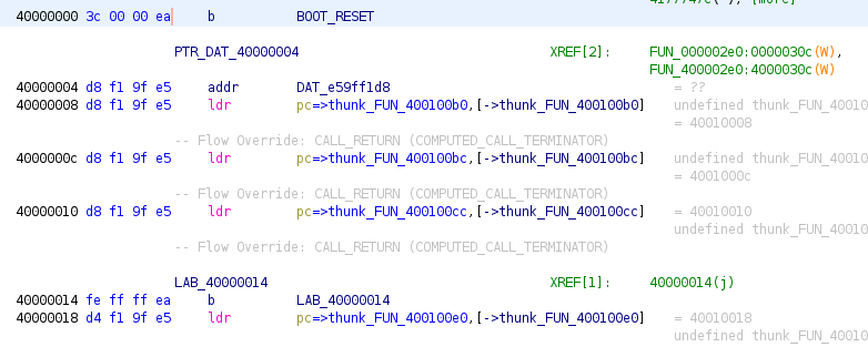
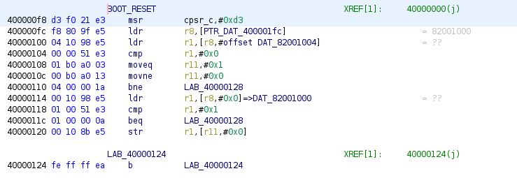
At the address 0x40000000, we see a branch statement that jumps to reset the firmware - that is to prepare initial environment for normal execution, e.g., setting up exception and interrupt vectors, initializing registers. Unfortunately, due to some missing peripherals, e.g., UART, I2C that an emulator may not be able to handle without knowledge, the whole emulation may get blocked as the following image dipected, where the program enters into 0x40000124, then loops forever.

Supporting a new CPU model
Although the example firmware was built at top of ARM Cortex-R7 processors, PANDA-QEMU does not support it yet, which requires a manual extension. The following command is to
- pull Avatar from Github an build its docker image
- run it in a container
- cline latest PANDA in this container, then build it locally after changes in extension are made
git clone https://github.com/avatartwo/avatar2.git
cd avatar && docker build -t avatar2 .
docker run --rm -it avatar2
sudo apt-get update
sudo apt install --no-install-recommends [dependencies]
git clone https://github.com/panda-re/panda.git
git checkout stable
[changes in extension]
mkdir -p build && cd build
../build.sh
The following changes are made to add a new cpu model in target/arm/cpu.c:
static const ARMCPUInfo arm_cpus[] = {
    ...
    { .name = "cortex-r5",   .initfn = cortex_r5_initfn },
    { .name = "cortex-r7",   .initfn = cortex_r7_initfn },
    ...
}

static void cortex_r7_initfn(Object *obj)
{
        ARMCPU *cpu = ARM_CPU(obj);
        cortex_r5_initfn(obj);
        cpu->pmsav7_dregion = 32;
}
A new cpu model cortex-r7 and its initialization function are added.
Initial emulation setting
Now, by writting a script, we create a list of dictionaries representing resolvable information about each section as explained previously.
entries = [{
"load_address":0x40010000,
"size":0x25479a0,
"offset": 0x2260,
"file":"modem.bin",
"name":"MAIN",
},
{"load_address":0x40000000,
"size": 0x1E40,
"offset": 0x420,
"file":"boot.bin",
"name":"BOOT",
},]
Next, resolve each entry, add a corresponding memory range, and load raw data into each range. Particularly, we configure entry point at 0x40000000 and a newly added cortex-r7 as the cpu model.
from avatar2 import *
from avatar2.peripherals import *
from types import SimpleNamespace

avatar = Avatar(arch=ARM, cpu_model='cortex-r7')
emu = avatar.add_target(PyPandaTarget, entry_address=0x40000000)

for e in entries:
    entry = SimpleNamespace(**e)
    avatar.add_memory_range(entry.load_address, entry.size, name=entry.name, permission='rwx')

avatar.init_targets()

for e in entries:
    entry = SimpleNamespace(**e)
    with open(entry.file, "rb") as f:
        f.seek(entry.offset, 0)
        data = f.read(entry.size)
        emu.write_memory(entry.load_address, entry.size, data, raw=True)
emu.bp(0x40000124)
emu.cont()
emu.wait()
print(f"Reach the breakpoint {hex(emu.regs.pc)}")
emu.cont()
emu.wait()
If we run this script, we see no output since the emulation may get blocked in some checking due to incorrect values in MMIO ranges managed by missing peripherals. For example, when we set a breakpoint at a deap loop located at 0x40000124, the avatar later hits then quits for timeout reason.
[PYPANDA] Panda args: [/usr/local/lib/python3.8/dist-packages/pandare/data/arm-softmmu/libpanda-arm.so -L /usr/local/lib/python3.8/dist-packages/pandare/data/pc-bios -machine configurable -kernel /tmp/tmpxurfxtjc_avatar/PyPandaTarget0_conf.json -gdb tcp::3333 -S -nographic -qmp tcp:127.0.0.1:3334,server,nowait -m 128M -monitor unix:/tmp/pypanda_mol8tnbyr,server,nowait]
Configurable: Adding processor cortex-r7
Configurable: Adding peripheral[avatar-rmemory] region logging-uart at address 0x84000000
Configurable: Adding memory region MAIN (size: 0x25479a0) at address 0x40010000
Configurable: Adding memory region BOOT (size: 0x1e40) at address 0x40000000
...
Reach the breakpoint 0x40000124
2024-04-04 10:26:18,317 | avatar.targets.PyPandaTarget0.GDBProtocol.INFO | Attempted to continue execution on the target. Received response: {'type': 'result', 'message': 'running', 'payload': None, 'token': 8, 'stream': 'stdout'}, returning True
2024-04-04 10:26:18,317 | avatar.targets.PyPandaTarget0.INFO | State changed to TargetStates.RUNNING
2024-04-04 10:26:18,318 | avatar.targets.PyPandaTarget0.INFO | State changed to TargetStates.BREAKPOINT
2024-04-04 10:26:18,318 | avatar.INFO | Received state update of target PyPandaTarget0 to TargetStates.RUNNING
2024-04-04 10:26:18,318 | avatar.INFO | Breakpoint hit for Target: PyPandaTarget0
2024-04-04 10:26:18,318 | avatar.INFO | Received state update of target PyPandaTarget0 to TargetStates.BREAKPOINT
2024-04-04 10:26:18,319 | avatar.targets.PyPandaTarget0.INFO | State changed to TargetStates.STOPPED
2024-04-04 10:26:18,319 | avatar.INFO | Received state update of target PyPandaTarget0 to TargetStates.STOPPED
2024-04-04 10:26:18,327 | avatar.targets.PyPandaTarget0.INFO | State changed to TargetStates.EXITED
2024-04-04 10:26:18,328 | avatar.INFO | Received state update of target PyPandaTarget0 to TargetStates.EXITED
After examinating boot section, we have identified that setting 0x40000400 as entry address could bypass this unresolvable checking. With a new setting, we are still not able to see any output because we did not handle UART peripheral, which is widely used throughout baseband firmware for debugging reason. So, in the next section, we will explain how to identify the MMIO range corresponding to UART peripheral.
Identifying UART’s MMIO range and emulating
Here is a trick by using the script provided by Grant to reconstruct function names. Having renamed functions, we successfully tell functions related to the UART protocol as following, where we see a distinct memory range in use from 0x84000000 to 0x84001000.
void uart_main_2(undefined4 param_1,undefined4 param_2,undefined4 param_3)
{
  ...
  iVar3 = thunk_FUN_04005b30(&DAT_4322638c,0,0x26c);
  *(undefined2 *)(iVar3 + 0x12) = 1;
  *(undefined **)(iVar3 + 0x74) = &LAB_405f9eda+1;
  *(undefined1 **)(iVar3 + 0x80) = &DAT_84000000;
  *(undefined2 *)(iVar3 + 0x84) = 0x32;
  iVar3 = thunk_FUN_04005b30(&DAT_432265f8,0,0x26c);
  *(undefined2 *)(iVar3 + 0x12) = 2;
  *(undefined **)(iVar3 + 0x74) = &LAB_405f9eda+1;
  *(undefined **)(iVar3 + 0x80) = &DAT_84001000;
  *(undefined2 *)(iVar3 + 0x84) = 0x33;
  iVar3 = thunk_FUN_04005b30(&DAT_43226864,0,0x26c);
  *(undefined2 *)(iVar3 + 0x12) = 4;
  *(undefined4 *)(iVar3 + 0x80) = 0;
  *(undefined **)(iVar3 + 0x74) = &LAB_405f9f80+1;
  ...
  FUN_405fa318();
}
However, we never saw any UART-specific write functions that have been renamed, and must manually identify these. We go back to 0x40000400 where we set a breakpoint, and see quite a few functions being called with a meaningful string, e.g., FUN_400009bc("\nMode=");. Keep examinating its sub function, we could find that FUN_4000096c works similar to putc function outputing one character into a serial terminal; In this function, DAT_84000018 indicates data presence in UART and DAT_84000000 is the actual data-transmit register.
void FUN_40000400(void)
{
   ...
   FUN_400009bc("\nMode=");
   ...
}

void FUN_400009bc(char *param_1)
{
  char cVar1;

  while (cVar1 = *param_1, cVar1 != '\0') {
    if (cVar1 == '\n') {
      FUN_4000096c(0xd);
    }
    FUN_4000096c(cVar1);
    param_1 = param_1 + 1;
  }
  return;
}

void FUN_4000096c(undefined param_1)
{
  do {
  } while ((DAT_84000018 & 0x20) != 0);
  if (499 < DAT_4b200c00) {
    DAT_84000000 = param_1;
    return;
  }
  DAT_84000000 = param_1;
  *(undefined *)((int)&DAT_4b200c04 + DAT_4b200c00) = param_1;
  DAT_4b200c00 = DAT_4b200c00 + 1;
  return;
}
Avatar2 offers a generic peripheral class to handle hardware interaction. We extend this class to create read and write functions that are associated with specific addresses in the memory range of the UART interface.
class UARPrf(AvatarPeripheral):
    def hw_read(self, offset, size, **kwargs):
        if offset == 0x18:
            return self.status
        return 0

    def hw_write(self, offset, size, value, **kwargs):
        if offset == 0:
            sys.stderr.write(chr(value & 0xff))
            sys.stderr.flush()
        else:
            pass
        return True

    def __init__(self, name, address, size, **kwargs):
        super().__init__(name, address, size, **kwargs)
        self.status = 0
        self.read_handler[0:size] = self.hw_read
        self.write_handler[0:size] = self.hw_write

# add this peripheral range before avatar.init_targets()
avatar.add_memory_range(0x84000000, 0x1000, name='logging-uart', emulate=UARPrf)
From now on, we are able to see output while the firmware is running. However, this program will crash because the current script can not handle all missing periperals. In this case, re-hosting approach will come into place, and I will have a deep-dive into it in futuric posts.
2024-04-04 10:40:40,015 | avatar.targets.PyPandaTarget0.RemoteMemoryProtocol.INFO | Successfully connected rmp
Unknown
0$: Trying to execute code outside RAM or ROM at 0x00000000
Shanno boot mode
The reason why we go back to 0x40000400 once again is to understand all boot modes. Here, we clearly observe that DUMP_MODE will crash the program once dumping is done; while BOOT_MODE is for normal start-up.
void FUN_40000400(void){
    if (unaff_r4 == &DUMP_MODE) {
        ...
        Crash_1();
    }
    else {
        // BOOT MODE
        if (unaff_r4 == (undefined *)0x424f4f54) {
            ...
            FUN_400002e0();
            FUN_400009bc("Boot\n");
        }
    }
}
Looking further into the whole firmware, we may have many checking like this and would like to lead the emulation forward by writing a satisfying guard value. We could be able to modify this value in the run time.
emu.bp(0x40000478)
emu.cont()
emu.wait()
print(f"Reach the breakpoint {hex(emu.regs.pc)}")
emu.regs.r4 = 0x424f4f54
emu.bp(0x400004c8)
emu.cont()
emu.wait()
print(f"Reach the breakpoint {hex(emu.regs.pc)}")
emu.write_memory(0x400004c8, 0x4, b"\x00\xf0\x20\xe3", raw=True)
emu.cont()
emu.wait()
Then the firmware could enter into BOOT_MODE, and we could see that Boot is present in the UART output.
Reach the breakpoint 0x40000478
...
Reach the breakpoint 0x400004c8
Boot
However, this approach does not work out in the dynamic analysis, since we need to modify for all potantial checking. The more general approach is to snapshot the current state, then attemp all possible values emitted by a fuzzing engine, which is called snapshot-based fuzz testing. A code example could be presented as following:
snapshot(avatar, snapshot_name)

while (emu.regs.pc != 0x400004d0):
    restore(avatar, snapshot_name)
    emu.regs.r4 = fuzz()
    emu.cont()
    emu.wait()
In the help of state snapshot, we could be able to explore the firmware logic in a more effective manner, and achieve a higher code coverage.
A function to snapshot CPU states could be written this way:
def snapshot(avatar, snapshot_name):
    peripherals = {}
    for mem in avatar.memory_ranges:
        if hasattr(mem.data, 'python_peripheral'):
            per = mem.data.python_peripheral
            print("Snapshotting " + str(per))
            peripherals[mem.begin] = per

    with open('avatar-snapshot-%s' % snapshot_name, 'wb') as fp:
        pickle.dump(peripherals, fp)
Ref
[1] Fuzzing against machine
[2] Breaking band - https://comsecuris.com/slides/recon2016-breaking_band.pdf
[3] Emulating Samsungs’ baseband - https://i.blackhat.com/USA-20/Wednesday/us-20-Hernandez-Emulating-Samsungs-Baseband-For-Security-Testing.pdf